The translucent materials are composed by many features but to recreate them we will focus on four of them ( with a very rough and short explanation ) :
Reflection
The light that bounces in the surface of the material.
Refraction
The light that passes through the material and get distorted.
Chromatic aberration
The distorsion in refraction caused by the diferent wavelenghts of the light.
Transmission
The amount of light that passes through the material.
 |
| Here is the final result! |
Refraction
We will need to make a custom refraction to be able to recreate the chromatic aberration in the material, so lets start with It.
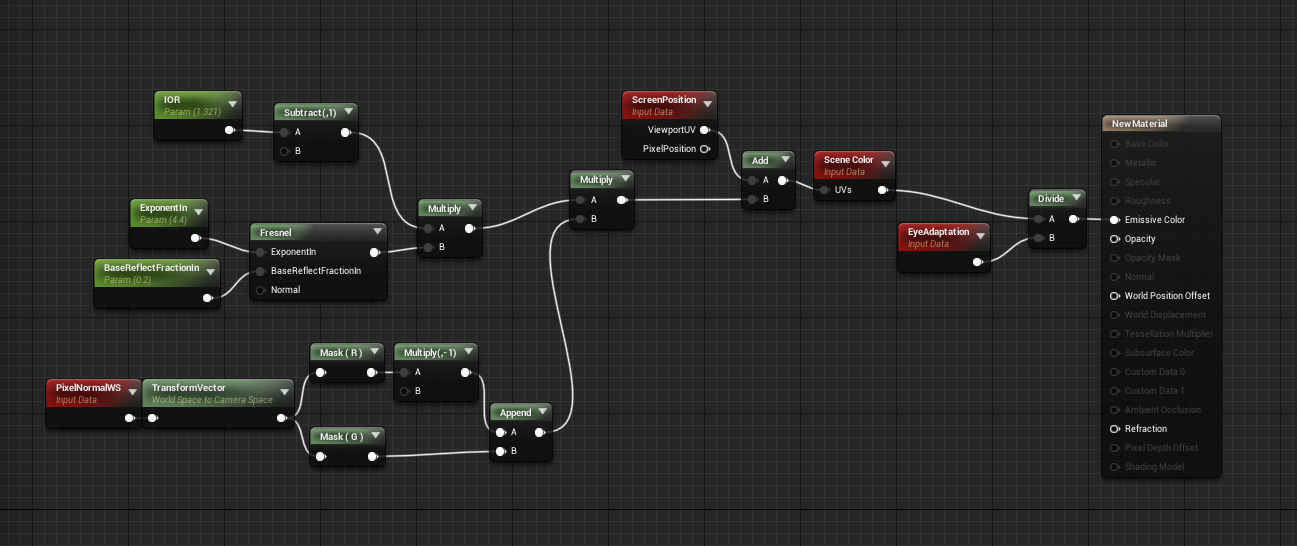
To achieve the effect we need the light information from the enviroment hitting the material, and to do this accurately we need to raytrace from each pixel taking into account the bending that the ray suffer when entering different materials. Fortunately there is a popular less expensive solution that most realtime engines use. This consists in taking the main image rendered before the translucency objects and deform it accordingly the surface normals, in most cases its a fantastic solution.
The basic way of calculating refraction is:
RefractedUV = ViewportUV + (RefractionIndex - 1) * ViewSpaceNormal.xy
This gives us the coordinates to sample the scene image. This scene image is called SceneColor. So we just have to take PixelNormalWS, transform it to camera space and invert the red channel to get the base coordinate distorsion. When added to the viewportUV and used as coordenates to sample the SceneColor, it should distord the background image accordingly the mesh surface.
 |
| If the material its too bright or too dark its because the post process eye adaption, we will solve this later. |

To match the intended intensity of emissive, we must divide it by EyeAdaption before conecting it to the material (otherwise it will be brighter or darker depending on overall scene luminance values when using eye adaption in post process).
*In very few cases it can be less than one

Unreal already have a distance blend node, but we will try to understand how it works:
Its composed by three main nodes, a sum, a division and a 0-1 clamp. The sum let us offset the input, so we can scale it with the division from wathever value we want. Higher values than 1 and lower than 0 will be clamped to 1 and 0, so we end un with a 0-1 range.
This simple but powerfull operation let us translate any range of values directly to a 0-1 range.
In this particular case, as unreal is in cm, getting the pixel depth give us the distance in cm to anything rendered in screen. Adding a value of 200 and dividing by 100 will give us a grayscale range from 2m to 3m from the camera.

This allows us to scale any value from a certain point. In this case
this will be usefull to tell the shader the distance to blend from one
value to another, but it has many more uses. There is actually a node
called constantBiasScale that is basically a sum and a multiplication
operation. This behaves the same way as the distance blend node without a
clamp. One of its many daily uses resides in passing texture values
from (0,1) to (-1,1). As often happen with custom packed normal maps or
noise textures applied to warp UVs.
Chromatic aberration
To achieve the chromatic aberration effect we will sample and tint the scene color a couple of times with a slightly different refraction value. This way, the more distorded the image, the more chromatic aberration. Instead of making two more distorded UVs from scratch, the best thing will be to take the base distorsion, multiply It by a low value, and add it to the final distorded UVs. I added a overall multiplier for all the refraction offsets so its easier to modify.
In this case, instead two base colors I use a third one to get a little extra artistic control over the chromatic aberration. The basic idea is take the scene texture tinted with the color we want, mainly red for a positive offsets, and blue for negative ones. Then we just add all the results and divide it by the overall number of results to get a 1:1 value to operate with the raw scene color. We make a max with the original scene color and we are ready to go!


Transmission
So now that we get the chromatic aberration ready Its time to make the transmission so we can control the amount of light that the material refract and Its color!
This is very simple, we just multiply the emissive output with a color parameter. For transmission a very cool looking effect Its to multiply the transmision by the clamped 0-1 fresnel+lowValue. Looks very good but It doesnt work with all shapes and sharp normals, so be aware It may be useful to disable It in some cases.
Reflection
Finally lets apply the reflection. Actually Its very easy to set up, just select translucency-> lighting mode -> Surface TranslucencyVolume and apply if you want the screen space refrections checkbox. Then create a Specular and a Roughness paramenters and set them to 1 and 0.1 (you can actually right click in any connector and promote to variable so the parameter get the same name as the conector input : D ).
Its an easy task, but I recommend do this last. The compiler takes ages to compile this translucent shading model so be aware that Its more useful to use the default one while experimenting for a fast iteration.

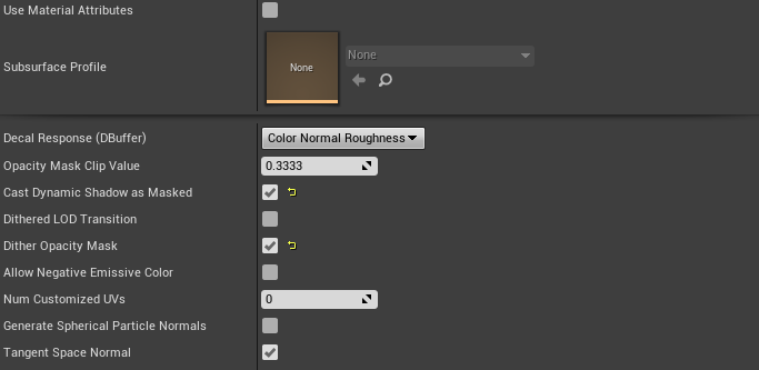
Shadows
There is no shadows as the default translucent material doesnt have one with dynamic light, but we can do a couple of tricks about this. First we can activate the mask dynamic shadow feature, this will tell the shadow pass to treat the translucent material as if It were masked. To take advantage of this, we will modify the opacity value when the shadow pass render the material so we get a default opacity value and a custom one for the shadow pass. To allow this we have to make a custom node with the following code “ return IsShadowDepthShader(); “. This will return 1 or 0 depending if its in shadow pass or not.

Now we can add a couple of features, first to get the overall shadow we take the blue channel of the transformed pixel normals we used to create the refraction to recreate the intensity of the refraction in the shadow. To do this we use the blue channel adjusted a little bit to fit our need and plug in in a ditherTemporalAA node as the alpha, so we get a smooth transition despite being a masked material.
We can improve It a little more by integrating the transmission and the IOR factor into the shadow. To do this Its enough to lerp between the inverse of the overall luminosity of the transmission (one minus desaturated) and our blue channel with an alpha of our IOR value( absolute and saturated so we dont screw the lerp values and dont get the shadow values inverted). I finally adjust a little bit the opacity by adding an adjusting transmission vale after the lerp. The shadow graph look like this:


Now we got a functional translucent material! A lot of features can be scaled down or up depending on quality/performance requirements, but overall its not a very heavy one (turning off shadow, simpler chromatic aberration, or improve it even more with blurred refraction acording the roughness!). But the first optimization will be to choose a less expensive translucency lighting mode as the current one is where the most shader instructions are. Here is how the final graph looks:


**Note that It has some bugs as a result of using the scene color, like refracting objects that are in front or reflecting the limits of the screen texture. This bugs could be less extreme by masking the objects in front checking the depth, or modifying the UVs so they compensate for the extra IOR cases where you can see the limits of the texture.
This will be all for now, maybe this bugs will be adressed in future entries. For now hope you like the post, and have fun with shaders!
Comments
Post a Comment